Camera Rotation with Double Zernikes
The way we deal with rotation in the updated code differs from the previous approach. It is important to understand that when we rotate the camera, there are two rotations that come into play: - Rotation of the field angle - Rotation of the sensor relative to the reference coordinate system.
We therefore need to be careful to distinguish between these two rotations.
Rotation of the sensor
To deal with the rotation of the sensor, we derotate the zernikes obtained with the Wavefront Estimation Pipeline (WEP) code. We do that by using the galsim.Zernike object. Since WEP provides zernike coefficients Z4-Z22, we add zeros to zernikes Z1-Z3 and then rotate them using the galsim.Zernike object rotation method. This ensures that whatever zernikes we use in state_estimator are derotated.
Rotation of the field angle
To account for the fact that after we have rotated the camera we are looking at another field angle position, we leverage the DoubleZernike object available in galsim. In this mode we use the double zernike sensitivity matrix and the DoubleZernike class in galsim, to compute the sensitivity matrix and the intrinsic zernikes at the rotated field angle.
Camera Rotation and Degree of Freedom
This document explains the relationship between the camera rotation and degree of freedom (DOF). When the wavefront sensor takes the images, the rotation angle (\(\theta\)) might not be zero and the calculated DOF needs to compensate for this, which means to rotate the DOF back to the reference plane (\(\theta = 0\)). It is the similar case for the hexapod position
Mirror Bending Mode
If the (x, y) coordinate plane rotates by an angle \(\theta\) in the counter-clockwise directon, the new coordinate system (x’, y’) is:
Since the measurement is on the (x’, y’) plane, the real value (x, y) should be:
Or rewrite the above formula as \(\vec{x} = \textbf{R}\vec{x}'\). The rotation matrix for 20 bending modes is \(\text{diag}([\textbf{R}, 1, \textbf{R}, \textbf{R}, \textbf{R}, 1, \textbf{R}, \textbf{R}, \textbf{R}, \textbf{R}])\)
Hexapod Position
For the camera rotation consider the figure below:
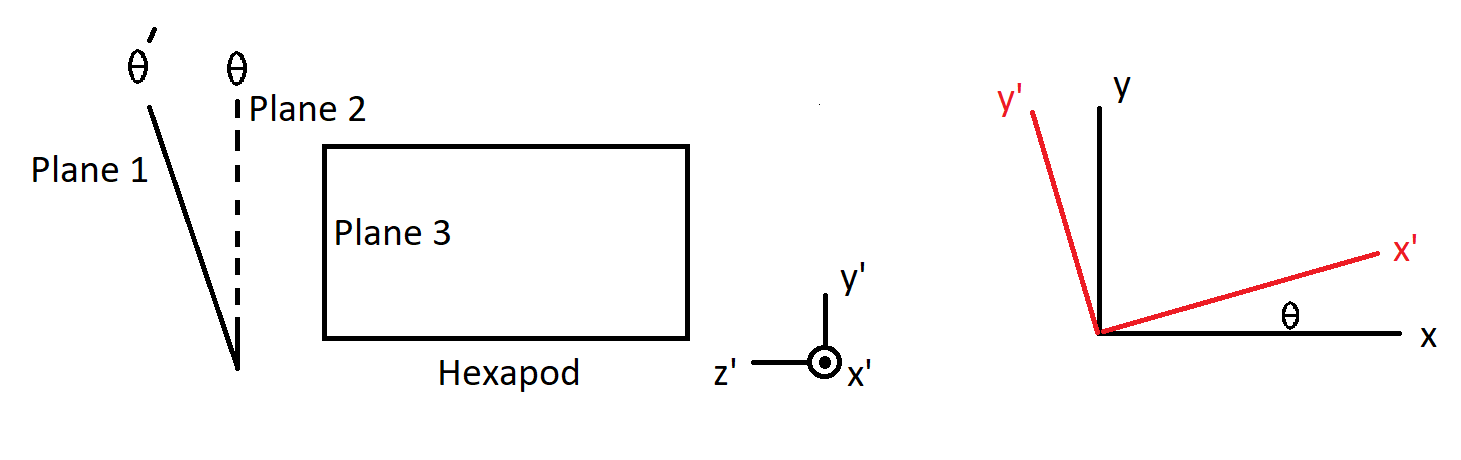
The rotation angle \(\theta'\) on the plane 1 transforms to the angle \(\theta\) on the plane 2 with a tilt rotation, which is tilt-\(x'\) here. The plane 2 is parallel to the plane 3, which is the face of hexapod. Basically, the first step is to get the relationship between \(\theta'\) and \(\theta\). Then, do the rotation between x, y-plane and x’, y’ plane.
The rotation matrix between x, y-plane and x’, y’-plane is:
For the camera hexapod, \(\theta'\) equals \(\theta\). For the M2 hexapod, consider the following figure:
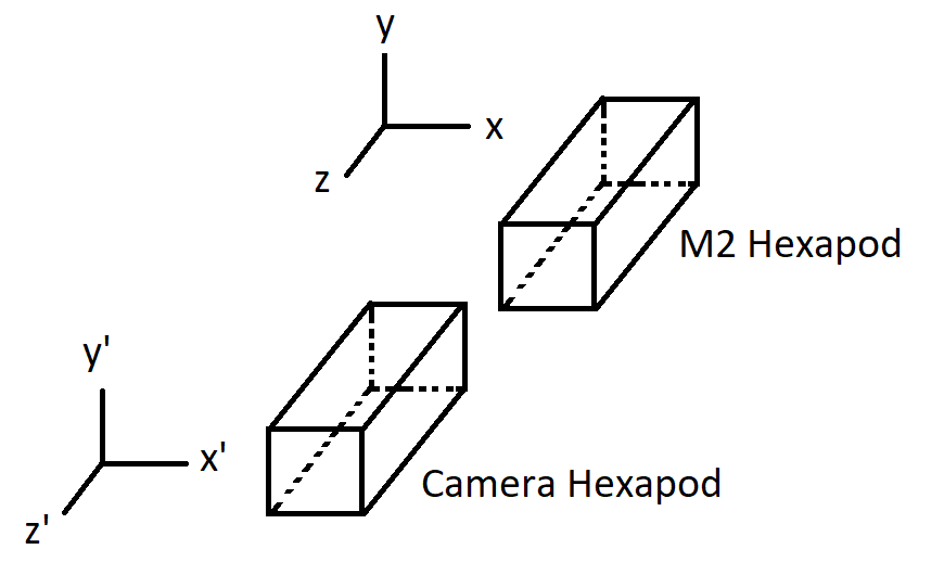
It is clear that the rotation angle \(\theta'\) on the x’, y’-plane will be the same as the rotation angle \(\theta\) on the x, y-plane if there is no tilt angle difference (e.g. \(r_{x}' = r_{x}\) and \(r_{y}' = r_{y}\)). It is noted that \(r_{z} = r_{z}' = 0\). In other words, \(\theta = f(\theta', \Delta r_{x}, \Delta r_{y})\) is a function of \(\theta'\), \(\Delta r_{x} = r_{x, \text{Cam}}'-r_{x, \text{M2}}\), and \(\Delta r_{y} = r_{y, \text{Cam}}'-r_{y, \text{M2}}\).
Based on Rodrigues’ rotation formula if a vector (\(\vec{v}\)) in \(\mathbb{R}^{3}\) is rotated by an angle \(\theta{\text{r}}\) about a unit vector \(\hat{r}\) according to the right-hand rule, the rotated vector (\(\vec{v}'\)) is:
Set \(\vec{v} = \cos(\theta)\hat{x} + \sin(\theta)\hat{y}\) and rotate \(\vec{v}\) by an angle \(\alpha\) about the axis \(\hat{x}\), we have:
Rotate the \(\vec{v}'\) by an angle \(\beta\) about the axis \(\hat{y}\), we have:
To get the angle \(\theta'\), we use:
Since the tilt angles are small based on LTS-206, assume \(\alpha = \delta_{1}\) and \(\beta = \delta_{2}\) with \(\delta{1}, \delta_{2} \ll 1\), we have:
If we consider the tilt angle difference between the camera rotator and camera hexapod, the above equation can be rewritten as
where \(\delta_{1/2,ref}\) is the tilt angle difference between the camera rotator and hexapod about \(x/y\). The details of the above calculation can follow: cam rot cal.pdf. To see the affection of rotation angle, assume \(\delta_{2} = \delta_{1,\text{ref}} = \delta_{2,\text{ref}} = 0\), we can plot the rotated angle as the following:
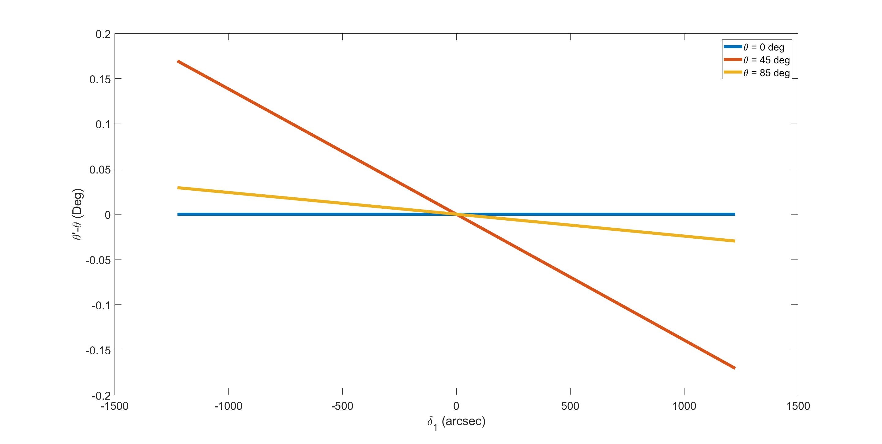
It is clear that the change of angle is small (\(< 0.2^{\circ}\)) since the range of the tilt angle is \(\pm 0.17^{\circ}\) according to the LTS-206. It is noted that in the real implementation, the reference of tilt angle is not considered (\(\delta_{1/2,\text{ref}} = 0\)) because it is believed that the values should be in the noise range.
Since the tilt angles between the camera and M1M3 are different, the above angle correction applies to M1M3 also. That means the rotation angle on the Mirror Bending Mode, is the corrected camera angle with \(\Delta r_{x} = r_{x, \text{Cam}}'-r_{x, \text{M1M3}}\) and \(\Delta r_{y} = r_{y, \text{Cam}}'-r_{y, \text{M1M3}}.\) The rotation angle can be simplified further to be \(\Delta r_{x} = r_{x, text{Cam}}'\) and \(\Delta r_{y} = r_{y, \text{Cam}}'\) because the relative coordinate system is used with the M1M3 as the reference point. And it is the similar correction for M2 bending mode.
* Some studies based on the affine transformation and Euler rotation are Coordinate Transformation.nb, Coordinate Transformation.pdf, Coordinate Transformation 2.nb, and Coordinate Transformation 2.pdf.